This blog series describe the selection, set-up and usage of a development environment for Zynq.
- Part 1 – Overview
- Part 2 – Set-Up the development environment
- Part 3 – Build boot files
- Part 4 – Boot Linaro from SD Card
- Part 5 – Programmable Logic projects with Vivado
- Part 6 – Eclipse Project for register access
Template project with AXI Lite support
The ARM architecture provide different processor interfaces. Zynq support AHB (Advanced High-performance Bus) and AXI (Advanced eXtensible Interface Bus).
Xilinx provide AXI Lite for setting and getting parameters of PL components. AXI Lite a reduced AXI interface.
Xilinx XPS include a nice Create or Import Peripheral (CIP) wizard. This wizard generate VDHL code for bus connections. For AXI Lite the CIP provide a register connection to read and write PL Registers from PS.
In Vivado 2013.2 the CIP Wizard was missing. Therefore I use Xilinx XPS to design a custom IP. With the newer Vivado Version it is possible to generate custom IPs under „Create and Package IP “ => „Create new AXI4 peripherial“.
Test project with AXI Lite support
Download under axi4_lite_test.
The project include three source files
- testbench.vhd
Simulate a AXI Lite Master to read and write the registers - axi4_lite_test.vhd
Top component with libraries to convert AXI Lite interface to a simpler bus interface - test_logic.vhd
Component with registers. Custom code should be places here
In axi4_lite_test.vhd I define new port signals in the entity
  port
  (
    D_IN					:  in  std_logic_vector(7 downto 0);
    D_OUT					:  out  std_logic_vector(7 downto 0);
    InteruptOut				: out std_logic;
...
The new signals were passed to the test_logic component.
  TEST_LOGIC_I : entity work.test_logic
    generic map
    (
      C_NUM_REG                      => USER_NUM_REG,
      C_SLV_DWIDTH                   => USER_SLV_DWIDTH
    )
    port map
    (
    D_IN					=>D_IN,
    D_OUT				=>D_OUT,
    InteruptOut			=>InteruptOut,
...
In test_logic.vhd we need to add this signals to the test_logic entity, too. So we can use the signals in the architecture of test_logic. Depending on the first register slv_reg0 and the input D_IN the output D_OUT is set. The extra signal InteruptOut is for later use.
  InteruptOut<=D_IN(0);

  D_OUT_PROC : process( slv_reg0,D_IN ) is
  begin
    case slv_reg0 is
      when x"00000000" => D_OUT <= D_IN;
      when x"00000001" => D_OUT <= not (D_IN);
      when x"00000002" => D_OUT <= "10101010";
      when x"00000003" => D_OUT <= "01010101";
      when others => D_OUT <= D_IN;
    end case;
  end process D_OUT_PROC ;
Normally a read and write to registers is possible and the read deliver the value written before. I following line change this behavior for register 1. Reading register 1 deliver the value of D_IN. Because D_IN includes only 8 signals I use the rest of register 1 to reach the read size of 32 bit.
when "01000000000000000000000000000000" => slv_ip2bus_data <= slv_reg1(31 downto 8) & D_IN;
Simulationg the testbench provide the results shown in following picture
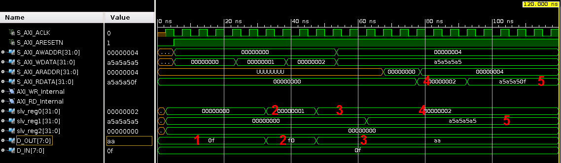
Marker:
- D_IN is provided as output D_OUT
- The value of slv_reg0 is changed to 1. D_OUT change to D_IN inverted
- The value of slv_reg0 is changed to 2. D_OUT change to a fix pattern
- The value of slv_reg0 is readed over AXI Lite
- The value of slv_reg1 is readed over AXI Lite. The last byte shows D_IN
Integrate your project in Zynq
Two ways are possible to bring your project in the hardware with Vivado.
- Build a core and connect it with PS in a design block
- Build a design block from PS, build a VHDL wrapper and connect it with your code
The second solution has the advantage that all can be integrated in one Vivado project. But much more coding is needed. For me it make sense to use a graphical tool on system level. Therefore I build a core and integrate it in Vivado.
Generating a core is very simple. Open your test project and select „Tools“=>“Package IP…“. Go further to „Choose IP Source Location“. Normally you can select „Package your project“. I have package it before, so this option is disabled. But you can insert the path to the project to open the IP package. Do not override it!
Open an new project and define your hardware. I use the zedboard. Use the tutorial creating-base-zynq-design-vivado-ipi-20132 to define a basic project.
Select „Project Settings“=>“IP“ and add your your test project as repository. Your IP should be visible in the lower section.
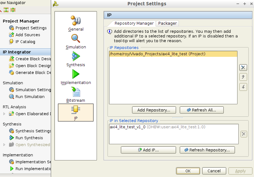
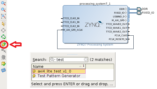
Your IP is added in the IP Catalog and you can add it to your design.
After adding your IP an banner open. Select „Run Connection Automation“ in the banner. Other IPs were added to connect your AXI interface with Zynq. Next step is to make IOs avaible from external. Select D_IN with right mouse button and select „Make External“. Do the same with D_OUT.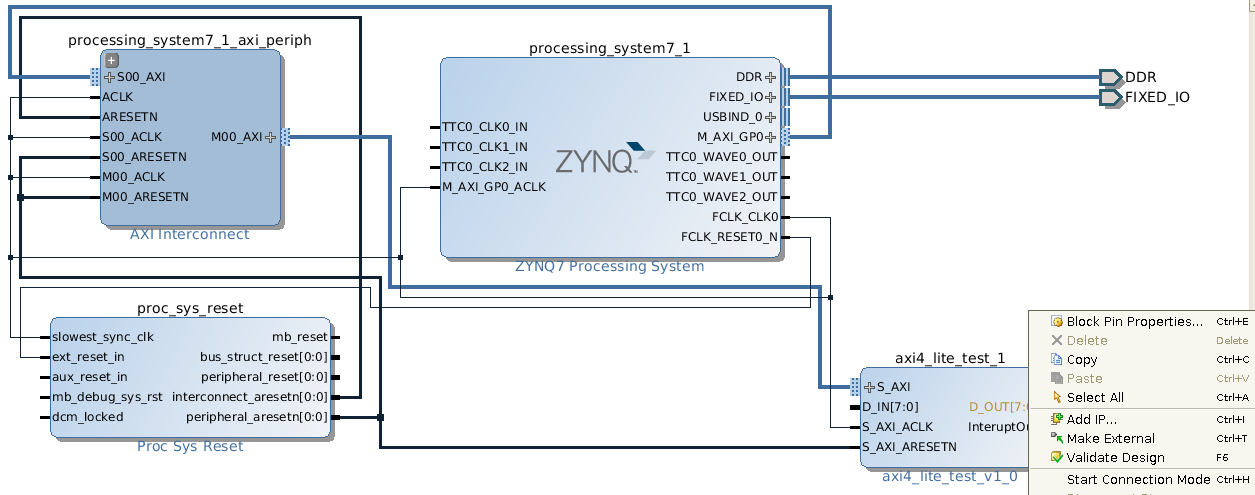
Last signal is InteruptOut. In any of my next post I will show how to handle a interrupt in Linux. Here we will only connect it to Zynq. Double click on the big Zynq block (processing_system7_1). Under „Interrupts“ activate „Fabric Interrupts“and „IRQ_F2P[15:0]“.
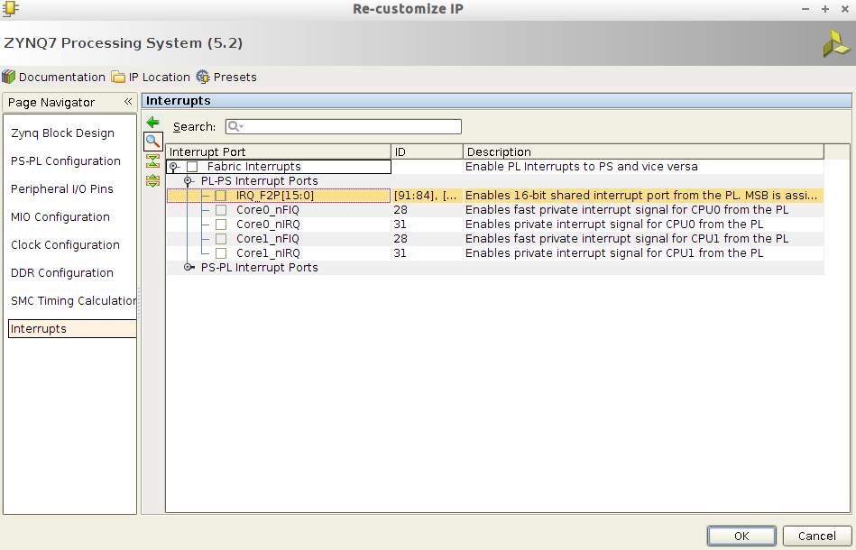
On my system this feature is buggy. The activation was only visible after closing the windows. Sometimes I have to do it two or three times. After successfully activation the Zynq has a new imput „IRQ_F2P[0:0]“. Connect InteruptOut to IRQ_F2P[0:0].
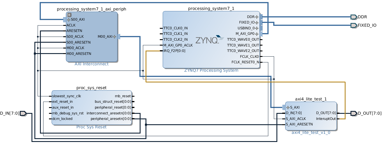
So we get the final design block. On last information is needed before we can syntheses and implement it. We have to connect the external signals to Zynq pins. We have select the board, so the enviroment can connect DDR and FIXED_IO automatically. Only D_IN and D_OUT are undefined.
The ucf file zedboard_master_UCF_RevC_v3.zip from zedboard homepage can not used with Vivado. For Vivado we need a xdc file. Select „Add Sources“=>“Add or Create Constraints“=>“Create File…“ to create a file named „Pins.xdc“. Copy the following information in the file and save it.
#  SW0
set_property iostandard "LVCMOS33" [get_ports "D_IN[0]"]
set_property PACKAGE_PIN "F22" [get_ports "D_IN[0]"]
set_property slew "slow" [get_ports "D_IN[0]"]
set_property drive "8" [get_ports "D_IN[0]"]
set_property PIO_DIRECTION "INPUT" [get_ports "D_IN[0]"]
#  SW1
set_property iostandard "LVCMOS33" [get_ports "D_IN[1]"]
set_property PACKAGE_PIN "G22" [get_ports "D_IN[1]"]
set_property slew "slow" [get_ports "D_IN[1]"]
set_property drive "8" [get_ports "D_IN[1]"]
set_property PIO_DIRECTION "INPUT" [get_ports "D_IN[1]"]
#  SW2
set_property iostandard "LVCMOS33" [get_ports "D_IN[2]"]
set_property PACKAGE_PIN "H22" [get_ports "D_IN[2]"]
set_property slew "slow" [get_ports "D_IN[2]"]
set_property drive "8" [get_ports "D_IN[2]"]
set_property PIO_DIRECTION "INPUT" [get_ports "D_IN[2]"]
#  SW3
set_property iostandard "LVCMOS33" [get_ports "D_IN[3]"]
set_property PACKAGE_PIN "F21" [get_ports "D_IN[3]"]
set_property slew "slow" [get_ports "D_IN[3]"]
set_property drive "8" [get_ports "D_IN[3]"]
set_property PIO_DIRECTION "INPUT" [get_ports "D_IN[3]"]
#  SW4
set_property iostandard "LVCMOS33" [get_ports "D_IN[4]"]
set_property PACKAGE_PIN "H19" [get_ports "D_IN[4]"]
set_property slew "slow" [get_ports "D_IN[4]"]
set_property drive "8" [get_ports "D_IN[4]"]
set_property PIO_DIRECTION "INPUT" [get_ports "D_IN[4]"]
#  SW5
set_property iostandard "LVCMOS33" [get_ports "D_IN[5]"]
set_property PACKAGE_PIN "H18" [get_ports "D_IN[5]"]
set_property slew "slow" [get_ports "D_IN[5]"]
set_property drive "8" [get_ports "D_IN[5]"]
set_property PIO_DIRECTION "INPUT" [get_ports "D_IN[5]"]
#  SW6
set_property iostandard "LVCMOS33" [get_ports "D_IN[6]"]
set_property PACKAGE_PIN "H17" [get_ports "D_IN[6]"]
set_property slew "slow" [get_ports "D_IN[6]"]
set_property drive "8" [get_ports "D_IN[6]"]
set_property PIO_DIRECTION "INPUT" [get_ports "D_IN[6]"]
#  SW7
set_property iostandard "LVCMOS33" [get_ports "D_IN[7]"]
set_property PACKAGE_PIN "M15" [get_ports "D_IN[7]"]
set_property slew "slow" [get_ports "D_IN[7]"]
set_property drive "8" [get_ports "D_IN[7]"]
set_property PIO_DIRECTION "INPUT" [get_ports "D_IN[7]"]

#  LED0
set_property iostandard "LVCMOS33" [get_ports "D_OUT[0]"]
set_property PACKAGE_PIN "T22" [get_ports "D_OUT[0]"]
set_property slew "slow" [get_ports "D_OUT[0]"]
set_property drive "8" [get_ports "D_OUT[0]"]
set_property PIO_DIRECTION "OUTPUT" [get_ports "D_OUT[0]"]
#  LED1
set_property iostandard "LVCMOS33" [get_ports "D_OUT[1]"]
set_property PACKAGE_PIN "T21" [get_ports "D_OUT[1]"]
set_property slew "slow" [get_ports "D_OUT[1]"]
set_property drive "8" [get_ports "D_OUT[1]"]
set_property PIO_DIRECTION "OUTPUT" [get_ports "D_OUT[1]"]
#  LED2
set_property iostandard "LVCMOS33" [get_ports "D_OUT[2]"]
set_property PACKAGE_PIN "U22" [get_ports "D_OUT[2]"]
set_property slew "slow" [get_ports "D_OUT[2]"]
set_property drive "8" [get_ports "D_OUT[2]"]
set_property PIO_DIRECTION "OUTPUT" [get_ports "D_OUT[2]"]
#  LED3
set_property iostandard "LVCMOS33" [get_ports "D_OUT[3]"]
set_property PACKAGE_PIN "U21" [get_ports "D_OUT[3]"]
set_property slew "slow" [get_ports "D_OUT[3]"]
set_property drive "8" [get_ports "D_OUT[3]"]
set_property PIO_DIRECTION "OUTPUT" [get_ports "D_OUT[3]"]
#  LED4
set_property iostandard "LVCMOS33" [get_ports "D_OUT[4]"]
set_property PACKAGE_PIN "V22" [get_ports "D_OUT[4]"]
set_property slew "slow" [get_ports "D_OUT[4]"]
set_property drive "8" [get_ports "D_OUT[4]"]
set_property PIO_DIRECTION "OUTPUT" [get_ports "D_OUT[4]"]
#  LED5
set_property iostandard "LVCMOS33" [get_ports "D_OUT[5]"]
set_property PACKAGE_PIN "W22" [get_ports "D_OUT[5]"]
set_property slew "slow" [get_ports "D_OUT[5]"]
set_property drive "8" [get_ports "D_OUT[5]"]
set_property PIO_DIRECTION "OUTPUT" [get_ports "D_OUT[5]"]
#  LED6
set_property iostandard "LVCMOS33" [get_ports "D_OUT[6]"]
set_property PACKAGE_PIN "U19" [get_ports "D_OUT[6]"]
set_property slew "slow" [get_ports "D_OUT[6]"]
set_property drive "8" [get_ports "D_OUT[6]"]
set_property PIO_DIRECTION "OUTPUT" [get_ports "D_OUT[6]"]
#  LED7
set_property iostandard "LVCMOS33" [get_ports "D_OUT[7]"]
set_property PACKAGE_PIN "U14" [get_ports "D_OUT[7]"]
set_property slew "slow" [get_ports "D_OUT[7]"]
set_property drive "8" [get_ports "D_OUT[7]"]
set_property PIO_DIRECTION "OUTPUT" [get_ports "D_OUT[7]"]
Now we are ready to build a bitfile. Use the explanation in Part 3 to build a Boot.bin file and test it.
Here are my files:
- ZedTest
Vivado project file - system.bit
bitfile generated with ZedTest - BOOT.BIN
bootfile generated from system.bit
BOOT.BIN and system.bit are included in Bootfiles.
Without software we only see that the LEDs and switches are connected (mode for slv_reg0 value 0). In the blog article Part 6 I show how to read and write registers from Linux without a device driver.